Oxide on My Wrist: Hubris on PineTime was the best worst idea
In my last Oxide-related post I got Oxide’s Propolis software running and said I might try and get their sled agent up and running next. Anyways that didn’t happen. Instead I ended up reading datasheets, writing rust codegen, spending 16 gigs of ram for an hour to build docs for a crate that’s just a glorified bundle of pointers, dreaming about serial data transfer, and uploading code to my smart watch over the slowest debug link I’ve ever had the displeasure of using. *Record Scratch* You’re probably wondering how I got in this situation. Well, it all started when I learned the nRF52832 microcontroller has a memory protection unit.
So yeah, I ported Oxide’s embedded kernel, Hubris, to my PineTime smart watch, and now I’m going to tell you about it. If you’re not into embedded dev much, stick around for a bit! It’s not all scary, but don’t feel bad if you have to bail as the tail end of this post descends into technical madness. If you are into embedded dev though, well, have I got a treat for you. Before I get into the how, I’m going to talk a bit about what Hubris is, why a smart watch is actually a good place to apply it, and some thoughts on things I like and things I don’t. Then I’ll tell you the tale of how I got it running on my hardware in particular. But first, a demo!
(twister math based on this pico8 demo by visy)
Also, if you’re just interested in the code, here’s my fork. The GPIO and SPI code are in a pretty good place, though I’m missing a couple hardware configuration options in both. Have fun!
Hubris: what?
I’m not the authority on the topic here, and if you want an explanation from someone who wrote the dang thing you should watch Cliff Biffle’s talk about it or read the transcript.
Let me give you the basics though, so you have some grounding. Hubris is a kernel for embedded devices that uses a hardware feature a lot of people have forgotten about: the Memory Protection Unit. This piece of hardware in many ARM and RISC-V chips allows the kernel to lock down whether various segments of memory are readable, writable, and executable. Then the kernel can execute a task in that limited context. And by the way, since all IO is memory mapped on these systems, memory protection and IO protection are the same thing. If you can’t access a peripheral’s address space, you can’t access that peripheral!
But hey, what’s the big deal right? We’re all used to this in operating systems like Linux, Windows, macOS, and so on. Well, in the embedded world, it may shock you to learn that most people are just out there shoving a bunch of tasks onto a chip with a kernel that doesn’t bother with this. Those tasks can absolutely stomp on each other’s memory, do whatever IO they want, set your cat on fire, it’s a free for all in there. Some other kernels provide MPU functionality, but pickings are slim.
Hubris says “that’s bad, actually”. The result is an architecture where tasks can only interact through message-passing. Hardware interaction is encapsulated in tasks too, which helps debugging a ton. For example, you can know with certainty that if something is toggling a GPIO pin, it’s the GPIO task. You can add debugging hooks into that task to trace what’s sending messages to it, and now you have a complete high level view of everything doing GPIO. You can enforce mutexes so that two tasks can’t both simultaneously ask the SPI task to do a data transmission at the same time. It’s fantastic.
Since Hubris is written in rust, it can also get the borrow checker in on the fun. Hubris extends the concept of borrow checking with a something called “Leases”. When a task sends a message to another task, it can include a Lease to some range of memory. As the recipient of a lease, you can’t access that memory directly, but you can ask the kernel to read or write that memory on your behalf. The kernel checks to make sure you’ve got a valid lease, and copies memory between your address space and the lease sender’s address space. Since rust’s borrow checker made sure the sender had the rights to hand out the lease in the first place, the whole thing is memory safe.
Oh yeah also they have a debugger called Humility, which knocked my programmer socks off. If you’ve got a debug link to your device you can use Humility to do things like get a list of running tasks, get a backtrace of a failing task, check out ringbuffer logs, mess around with GPIO/SPI/i2c. You can go even more extreme by asking it for your tasks’ memory spaces, and then start mucking around reading or writing bytes directly in memory.
Look at this backtrace I got debugging my demo code:
vi@navi ~/p/hubris (pinetime) [1]> cargo xtask humility app/demo-pinetime/app.toml -- tasks -sl lcd
    Finished dev [optimized + debuginfo] target(s) in 3.34s
     Running `target/debug/xtask humility app/demo-pinetime/app.toml -- tasks -sl lcd`
humility: attached via OpenOCD
system time = 129006
ID TASK                 GEN PRI STATE
 3 lcd                   61   3 FAULT: PANIC (was: ready)
   |
   +--->  0x20002208 0x00008cb2 userlib::sys_panic_stub
                     @ /hubris//sys/userlib/src/lib.rs:989
          0x20002210 0x00008cb8 userlib::sys_panic
                     @ /hubris//sys/userlib/src/lib.rs:981
          0x20002210 0x00008cc0 rust_begin_unwind
                     @ /hubris//sys/userlib/src/lib.rs:1444
          0x20002218 0x000086ce core::panicking::panic_fmt
                     @ /rustc/ac2d9fc509e36d1b32513744adf58c34bcc4f43c//library/core/src/panicking.rs:88
          0x20002220 0x0000898a core::panicking::panic
                     @ /rustc/ac2d9fc509e36d1b32513744adf58c34bcc4f43c//library/core/src/panicking.rs:39
          0x20002380 0x000084f6 main
                     @ /hubris//task/pinetime-lcd/src/main.rs:113
If this seems like a boring ol’ stack trace, yeah, that’s what’s so exciting! Boring ol’ stack traces are typically not this easy to get ahold of in the embedded world, and I’ll admit I’ve stuck to printf debugging in the past rather than deal with the other debugging tools available. This is so easy that even I don’t have an excuse anymore.
Oops, Hubris on a smart watch is actually practical
I fully expected everything I did with Oxide software to be fun, but otherwise impractical for hobbyist projects at home. Hubris is different.
See, on a smart watch, you want to be able to load a bunch of apps onto your watch without worrying if the timer app you just installed is actually counting its way down to nuking your EEPROM, putting you into a bootloop, and texting your ex. At the extreme end, a particularly unlucky piece of code could soft-brick your watch until you unglue the back (breaking the watertight seal), plug a programmer into the debug port, and reprogram it. But even if it never gets that bad, it’s just nice to not have to treat any extra piece of software as a land mine.
Enter, Hubris. Tasks isolated from each other? Done. Tasks isolated from hardware? yup! That’s all the foundation you need to start building a robust watch operating system. Get yourself some dedicated tasks for stuff like input, graphics compositing, bluetooth, and baby you’ve got a stew going!
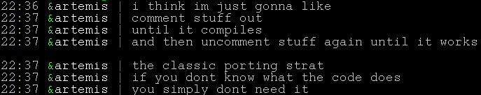
But should you use it yet?
It depends how adventurous you are, and how much you’re willing to do without support. To quote Hubris’ CONTRIBUTING.md:
However, Hubris is not done, or even ready. It’s probably not a good fit for your use case, because it’s not yet a good fit for our use case!
… snip …
and so, we thought it was important to explain where we’re currently at, and manage your expectations.
- We are a small company.
- Our current goal is to get our first generation products finished and in customers’ hands.
- We’re writing Hubris in support of that goal, not as its own thing. Hubris has a total of zero full time engineers – we’re all working on the products, and tool development is a side effect.
- For expediency, we’re developing our server firmware and Hubris in the same repo. We will probably split this up later to make it more obvious how to use Hubris from other applications. But, for now, we’re primarily focused on getting our firmware ready, because, again, we need to finish our computers.
- These points together mean that we may not have enough bandwidth to review and integrate outside PRs right now. This will change in the future.
So, you shouldn’t expect support, and you shouldn’t expect someone to be available to walk you through things personally.
On the other hand, everything I did in this post, and everything I learned along the way, came almost entirely from reading the existing docs (they’re good!) and the source code (it’s good too! and commented!). I got some helpful hints along the way from Oxide folks on twitter, but I went out of my way to figure out as much as possible on my own to see if it was possible. If you’re comfortable with that, and you’re fine with using an early stage project that’s still being molded into its final form, I’m happy to report there’s nothing stopping you from using Hubris right now!
The downside to hardware isolation.

Leases are great, but they’ve got overhead:
- You’ve got to round trip through the kernel for memory accesses
- The kernel has to file its taxes to make sure you’re allowed to access the lease in question
- The kernel has to copy memory between the two tasks’ memory spaces
The first two points here are somewhat mitigated by the LeaseBufReader/LeaseBufWriter wrappers that buffer read/writes and batch the kernel calls, but this just trades CPU time for RAM, something microcontrollers famously don’t have very much of.
And of course, the message passing itself trips through the kernel and has a cost, and the SPI task has its own taxes it needs to file to work generically.
I ran into this head first when working on my graphics demo. My display is connected over a 8MHz link and uses 16-bit color, so in theory I should be able to update half the screen at 16fps, if my code did nothing else. In reality, I was getting somewhere from 1-4fps with my LCD task talking to the SPI task, sending six write messages per row of pixels. I could reduce this overhead by buffering more pixels before handing them over to the SPI task, but now I’m spending more ram, and the memcopy isn’t free either. None of this even accounts for all the GPIO messages that are sent to the GPIO task during this from both the SPI task and my LCD code.
The easy solution to this is to give the LCD task direct access to the low level hardware peripheral rather than isolating it, but there’s more than just the LCD on that SPI bus; there’s some flash memory on there too. I’m left with a choice:
- Consume more ram, cut down overhead a bit, still have slower LCD access, but keep hardware isolation
- Cut the generic SPI middletask out of the equation, and roll LCD and Flash access into a single monolithic task that Does Both Directly For Some Reason.
- Deal with the low bandwidth and keep things as they are now.
The second option here is probably what I’ll do if I keep working on this project, because LCD speed is more important than a clean separation of concerns when you’re dealing with real time user interactions. Compare these two videos of writing a solid block of color to the screen, first through the SPI task, and second with direct SPI hardware access:
The second video is a bit flickery, so fair warning.
It sucks that this is a compromise I have to make. I have some weird ideas to partially mitigate the issue by creating a DMA-compatibly memory buffer in my LCD task and shoving a pointer to that through the SPI task and into the DMA SPI hardware, but I’m pretty sure this violates memory safety, and the only thing it would mitigate is the Lease overhead. Even if this worked, I’d still be stuck with large pixel buffers I don’t want or need.
I’m certain this is a challenge the Hubris folks are aware of (hey, if you’re reading and I’m missing something obvious, let me know and I’ll update the post). I’m interested to see what their solutions to this look like, or if they’re just using faster chips than me.
Intermission
Good gods I sure am writing a lot of words. I’ve been working on this for the past two weeks and it turns out I’ve got a lot to say! From this point on I’ll be talking about how I got to where I am now, the random bullshit I ran into, and how I solved it. If you’re curious about what porting Hubris to a new chip family looks like, this is for you. I also recommend checking out the commit history to see how I got here framed in code. I’ve left the commit history messy so you can see all the trials and missteps along the way.
So you want to port Hubris to a new chip
I came into this knowing absolutely nothing about Hubris, and I’m going to give this to you from that perspective, so you can see this project with fresh eyes the way I did. The first thing I did was run the first command in the README that looked vaguely useful.
cargo xtask dist app/demo-stm32f4-discovery/app.toml
stm32 is a family of arm microcontrollers that I recognize, so I started there. This command built a bunch of stuff in the drv/ and task/ folder, and generated a binary ready to flash onto a chip. drv/ and task/ have a bunch of drivers and application-level tasks respectively, but what’s in the app.toml? Well, here’s a link to see for your self. Among other things we’ve got
- The chip and board the app is intended to run on.
- The memory layout of the app.
- What tasks the app wants to include.
- Some runtime configuration switches.
A lot of the tasks I can tell I don’t need. Ping and pong look like test heartbeat apps and usart serial isn’t going to do me much good right now so I guess that’s out. Eventually we get down to three tasks that we do actually want running: hiffy, jefe, and idle.
Hiffy is the “HIF Interpreter”. I’ll let task/hiffy/src/main.rs do the talking:
//! HIF is the Hubris/Humility Interchange Format, a simple stack-based
//! machine that allows for some dynamic programmability of Hubris.  In
//! particular, this task provides a HIF interpreter to allow for Humility
//! commands like `humility i2c`, `humility pmbus` and `humility jefe`.  The
//! debugger places HIF in [`HIFFY_TEXT`], and then indicates that text is
//! present by incrementing [`HIFFY_KICK`].  This task executes the specified
//! HIF, with the return stack located in [`HIFFY_RSTACK`].
Then, according to task/jefe/README.mkdn, jefe is “the supervisory task for the demo application, which handles last-ditch error reporting, task restarting, and the like.”.
Finally, idle is scheduled when nothing else needs to run. Its sole purpose is to do nothing. Gods I wish that were me.
Bringing up the kernel
The PineTime uses an nRF52832 microprocessor, a lil baby 64MHz ARM chip with bluetooth. Hubris doesn’t have any support for it in the upstream repo so I added my own support. How did I do that? Well I woke up one morning, put on some lofi beats to write embedded software to, and over the next few hours I
- copied the
app/demo-stm32f4-discovery/folder toapp/demo-pinetime/. - renamed everything inside to pinetime.
- added
app/demo-pinetimeto theworkspace.membersof the top levelCargo.toml - copied the
chips/stm32f4.tomlfile tochips/nRF52832.toml, leaving the values there alone for now. - adjusted the flash/ram addresses in
app.tomlaccording to the nRF52832 datasheet. - commented out tasks so I only had
jefe,hiffy, andidle. - adjusted the imports in the
app/demo-pinetime/to import the nRF52832 hardware crates instead of the stm stuff. - messed around with the openocd config file until it worked with my BusPirate.
- flashed
target/demo-pinetime/dist/final.binto the watch. - it worked???
It’s incredible what you can do when you’re working with code that’s designed to be portable. The most important bit of this was the memory address adjustments. Chip datasheets will tell you the memory layout of your chip and your compiler and linker would really like to know this information. Here’s a screenshot from the nRF docs:
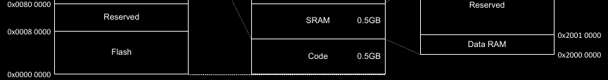
And then, here’s the corresponding bits in the app.toml:
vi@navi ~/p/hubris (pinetime)> cat app/demo-pinetime/app.toml
# bla bla bla
[outputs.flash]
address = 0x0000_0000
size = 0x0008_0000
read = true
execute = true

[outputs.ram]
address = 0x2000_0000
size = 0x0001_0000
read = true
write = true
execute = true
# bla bla bla
Neat right?
By the way, don’t use a BusPirate for flashing chips if you have something better. I love this thing and it’s a great little multi-tool but it took, no exaggeration, 15 minutes to finish uploading the firmware. I actually did it manually instead of using GDB because I was convinced GDB was just bugging out on me but in retrospect I just never gave it enough time to finish the upload. I have since purchased some proper flashing hardware and I’ll be very happy when it gets here.
Anyway, now I had a kernel doing fuck-all on a smart watch and I was incredibly full of myself. I went to twitter to claim victory like I had just cut off the hydra’s head, utterly clueless to the fate I’d just consigned myself to. See, I wasn’t content to just run a kernel. I wanted to drive the display, which means I needed to talk to the display controller. For that I needed to implement an SPI task, and in turn that lead to a GPIO task. At this point my yak stack was looking pretty tall, but the only thing to do was start shearing.
GPIO
Continuing the pattern of copy-pasting code and hammering it into submission, I copied the drv/stm32xx-sys, drv/stm32xx-sys-api, and drv/stm32xx-gpio-common folders, renaming the prefix to nrf52832. I also added these to the root-level Cargo.toml’s workspace just like with the app folder. For the rest of this post I’m going to leave that bit out, but basically, any time you’ve got a new Cargo.toml in a subdirectory you probably need to add its folder to the workspace.
The stm32xx-sys task handles GPIO and RCC configuration. These used to be separate but were merged into a single task to reduce memory usage, since every additional task costs some extra memory overhead. I didn’t know that at the time, but I did know my chip’s spec sheet doesn’t mention a direct corollary to the RCC, so I renamed my -sys folders back to -gpio and deleted all the references to RCC in the code.
The stm32 chips also have more GPIO configuration options than my nRF52832, and multiple GPIO banks. We don’t have to deal with that on the nRF chip so I cleared all that out too and reworked the API a bit to match.
The status quo of bare metal rust. Like, really bare metal
If you’ve worked with something like Arduino before you’re accustomed to having some reasonably efficient abstraction over the hardware that’s stable across different CPUs. These abstractions save you from looking up chip-specific tutorials or spec sheets to do something basic. That’s true in rust too if you use the Hardware Abstraction Layer (hal) crates, but with hubris we don’t have that luxury, because those crates assume they’re working without any sort of memory protection or CPU privilege system in place. Instead, we go a layer deeper and use Peripheral Access (pac) crates. These are auto-generated from individual chip descriptions and give a type-safe way to access chip registers with niceties like enums for multi-choice options. Here’s an example from the GPIO:
use nrf52832_pac as device;

// GPIO port 0 register set
let p0 = unsafe { &*device::P0::ptr() };

// Configure pin 2 as an output with pullup resistor
self.p0.pin_cnf[2].write(|w| {
  w
    .dir().variant(device::p0::pin_cnf::DIR_A::OUTPUT)
    .pull().variant(device::p0::pin_cnf::PULL_A::PULLUP)
});
These writers let you modify multiple fields in the same 32-bit hardware register without having to juggle a bunch of integer constants and bitwise operations. It’s pretty nice actually! The downside is these crates get pretty large, and some of them don’t even have proper docs on docs.rs. See this incredibly broken set of stm32h7 docs for example. It’s not that there’s anything complicated about the build itself, it’s just that it consumes so much resources the docs.rs backend is killing off the docs mid-build. I built the docs for this crate in particular on the big chonker I used for my last post on Propolis, and it took 16 gigs of ram and an hour real-time. The nRF52832 pac crate is fine on docs.rs, but you may have to build docs locally depending on what chip you’re working with.
Anyways, on with the show.
But wait there’s codegen
The final piece to get this all compiling was the .idol file, something I hadn’t noticed up until this point. These files describe the message passing API surface of a task, so any time you make changes to that API you’ve got to update the .idol file too. Once again I duplicated the stm32’s sys idol file to a gpio idol file for my chip, and here’s a sample of what that looks like:
Interface(
    name: "GPIO",
    ops: {
        "gpio_configure_raw": (
            args: {
                "pin": "u8",
                "config": "u32",
            },
            reply: Result(
                ok: "()",
                err: CLike("GpioError"),
            ),
            idempotent: true,
        ),
        "gpio_configure_gourmet": (
            args: {
                "pin": "u8",
                "mode": (
                    type: "Mode",
                    recv: FromPrimitive("u8"),
                ),
                "output_type": (
                    type: "OutputType",
                    recv: FromPrimitive("u8"),
                ),
                "pull": (
                    type: "Pull",
                    recv: FromPrimitive("u8"),
                ),
            },
            reply: Result(
                ok: "()",
                err: CLike("GpioError"),
            ),
            idempotent: true,
        ),
    }
)
The nrf52832-gpio crate uses this at compile time to generate the server trait for you to implement, and the nrf52832-gpio-api crate generates a corresponding client stub to plumb the inner workings of talking to that server. All a server has to do is implement the appropriate trait and provide a main function that pumps the message queue. Clients just import the api crate and call the api like a function, with the inter-task communication hidden away when you don’t want to think about it.
Once I updated my idol file and pointed my build.rs files at it, I had a working GPIO task! All I had to do was add it to my app.toml and I was good to go. Or, so I thought. I had actually missed something very important, but to figure that out I had to try and use my GPIO for something.
Starting the LCD task
With a GPIO task up and running, I had enough to actually make my watch do something visible. The LCD backlight is just controlled by some GPIO pins, so I whipped up a quick LCD task to make it blink.
To do this, I copied task/pong over to task/pinetime-lcd and stripped out everything from the main loop except for what looked like some sleep code (it was!). I also replaced the USER_LEDS task slot with GPIO, imported the GPIO api, and sprinkled in some GPIO control of the backlight pin.
#![no_std]
#![no_main]
use userlib::*;
use drv_nrf52832_gpio_api as gpio_api;
task_slot!(GPIO, gpio);
#[export_name = "main"]
pub fn main() -> ! {
    const TIMER_NOTIFICATION: u32 = 1;
    const INTERVAL: u64 = 3000;
    const BACKLIGHT_HIGH = 23;

    // Get handle to talk to the gpio task
    let gpio = gpio_api::GPIO::from(GPIO.get_task_id());

    // Configure pin for output
    gpio.gpio_configure_output(BACKLIGHT_HIGH, gpio_api::OutputType::PushPull, gpio_api::Pull::None).unwrap();


    let mut msg = [0; 16];
    let mut deadline = INTERVAL;
    sys_set_timer(Some(deadline), TIMER_NOTIFICATION);
    loop {
        let msginfo = sys_recv_open(&mut msg, TIMER_NOTIFICATION);

        // Toggle backlight
        gpio.gpio_toggle(1 << BACKLIGHT_HIGH).unwrap();

        if msginfo.sender == TaskId::KERNEL {
            deadline += INTERVAL;
            sys_set_timer(Some(deadline), TIMER_NOTIFICATION);
        }
    }
}
Then it was the song and dance of updating my Cargo.toml and my app.toml. Here we get to see task slots for the first time! I’ll give you the abridged version from the app.toml:
[tasks.gpio]
# all the gpio config

[tasks.lcd]
# all the lcd config, but then
task-slots = ["gpio"]
So to recap,
- The rust code declares a task slot with
task_slot!(GPIO, gpio); - In our
app.toml, we declare agpiotask - we fill the LCD task’s
gpioslot with that GPIO task. - At run time, the task slot provides the GPIO task’s ID, and the rust code uses that to build a client struct to talk to GPIO.
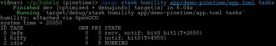
Excellent, surely this works right? Well, uh, no. And … this GENeration number in humility tasks seems to keep going up. I think my GPIO task is crashing, and my .unwrap()s are taking the LCD down with it.
vi@navi ~/p/hubris (pinetime)> cargo xtask humility app/demo-pinetime/app.toml tasks
    Finished dev [optimized + debuginfo] target(s) in 3.41s
     Running `target/debug/xtask humility app/demo-pinetime/app.toml tasks`
humility: attached via OpenOCD
system time = 183050
ID TASK                 GEN PRI STATE
 0 jefe                   0   0 recv, notif: bit0
 1 gpio              315251   1 recv
 2 lcd               318758   3 not started
 3 hiffy                  0   3 ready
 4 idle                   0   5 ready
Trust no one, not even yourself
This, my friends, is the memory protection unit in action. There’s one little detail I didn’t mention in the GPIO section earlier, because I had forgotten it myself: we need to give our GPIO task access to the memory space of the GPIO peripheral. If we don’t, the MPU shows up and unalives our little GPIO task with no feelings of remorse.
Finally, we learn that this is what that chips/ folder is for. Every entry in our chips/nRF52832.toml defines the address and size of some memory block, and gives that block a name we can use to let tasks use it. So for GPIO, I added this to my chips file:
[gpio]
address = 0x5000_0000
size = 0x1000
And in my app.toml, I added
[tasks.gpio]
# The name of the memory range doesn't have to be the same as the task name, but in this case it is.
uses = ["gpio"]
With that, we have a glorious blinky screen!
SPI’s sappin’ my sanity
The next thing to do is to actually turn the screen on and get some pixel data on there, and for that we need SPI. SPI is a serial protocol whereby one host device (our microcontroller) is connected to several client devices (our LCD, also some SPI flash memory) over three shared lines carrying bidirectional data and a clock signal. Each client device also has a dedicated chip-select signal which is pulled low to tell that device it’s being addressed and pulled high to tell it to ignore whatever’s going on on the line. Our display is connected over a SPI link, and our microcontroller has dedicated SPI hardware to use that link efficiently. We just need to write some code to use the SPI hardware.
Once again, I copied the stm32 SPI driver and started chopping away at the parts I didn’t need, since the nRF has much simpler SPI hardware with less configuration involved. It’s got two ways to use the SPI, Direct Memory Access (DMA) and the simpler register-driven variant. DMA is more efficient because we can point the SPI hardware at a large chunk of memory, tell it to go to town on that memory, and then yield to other tasks for a bit. The downside is, it’s more complicated to use. In the interest of Getting Something Working I used the simpler SPI interface that need us to feed in bytes one at a time as they’re transmitted.
Here’s where things got complicated though, not because of the SPI hardware, but the configuration around it. Our app.toml provides task configuration sections that our tasks can read at build time. The SPI driver I copied converts this configuration to a struct with all the device and mux configuration. This involves walking the toml data, validating that it is indeed a satisfiable configuration, and generating rust code to represent that configuration. I’ve never actually done rust codegen until now, but it’s not too dissimilar from something like Haskell codegen, so that part didn’t scare me off too bad.
What did cause me a headache though was this cursed error report:
error: failed to run custom build command for `drv-nrf52832-spi-server v0.1.0 (/sd/vi/home/p/hubris/drv/nrf52832-spi-server)`

Caused by:
  process didn't exit successfully: `/sd/vi/home/p/hubris/target/release/build/drv-nrf52832-spi-server-b7d1371bb53586d5/build-script-build` (exit status: 1)
  --- stdout
  --- toml for $HUBRIS_TASK_CONFIG ---
  [spi]
  global_config = "spi1"

  cargo:rerun-if-env-changed=HUBRIS_TASK_CONFIG

  --- stderr
  Error: environment variable not found

  Stack backtrace:
     0: anyhow::error::<impl core::convert::From<E> for anyhow::Error>::from
               at /home/vi/.cargo/registry/src/github.com-1285ae84e5963aae/anyhow-1.0.44/src/error.rs:530:25
     1: <core::result::Result<T,F> as core::ops::try_trait::FromResidual<core::result::Result<core::convert::Infallible,E>>>::from_residual
               at /rustc/ac2d9fc509e36d1b32513744adf58c34bcc4f43c/library/core/src/result.rs:1915:27
     2: build_util::toml_from_env
               at /sd/vi/home/p/hubris/build/util/src/lib.rs:60:18
     3: build_util::config
               at /sd/vi/home/p/hubris/build/util/src/lib.rs:51:5
     4: build_script_build::main
               at ./build.rs:17:25
Huh? The failing line is simply let global_config = build_util::config::<GlobalConfig>()?;.
A couple hours later and I finally found the culprit. The original app I copied didn’t have any SPI, and when I was looking at the other ones that did I missed a config section down at the bottom with keys like [config.spi.spi1]. That global_config setting tells the build system what key actually holds the SPI configuration details, and if that key isn’t actually present you get the cryptic error message above about missing environment variables.
Eventually though I did get SPI up and running, and you can see a sample of the config for that below. I’m pretty happy with where the implementation is now after a few more days of refactoring and refining it down, but it could stand for doing a DMA version at some point.
[config]

[config.spi.spi0]
controller = 0

[config.spi.spi0.mux_options.lcd]
miso_pin = 4
mosi_pin = 3
sck_pin = 2

[config.spi.spi0.devices.lcd]
mux = "lcd"
cs = 25
frequency = "M8"
spi_mode = 3
Pixels pixels pixels pixels pixels
With SPI working I could start getting pixels on the screen. This is a simple case of “read the datasheet and do what it says”. The display controller in here is also very similar to the ones they have on the TI-84+CSE, something I have a history of working with, so I was right at home with it. No interlacing on this one though sadly, so I can’t do the half-resolution hack to squeeze more performance out of it. Commands are sent by holding the command pin low and sending the 8-bit command code over the serial bus, and then command data comes after with the command pin held high. I’m using 16-bit color, but it can accept 12-bit color to save bandwidth. The downside is you’ve got to worry about byte alignment, and that’s a pain.
Eventually I got a funky lil guy on my screen surrounded by undefined RAM data:
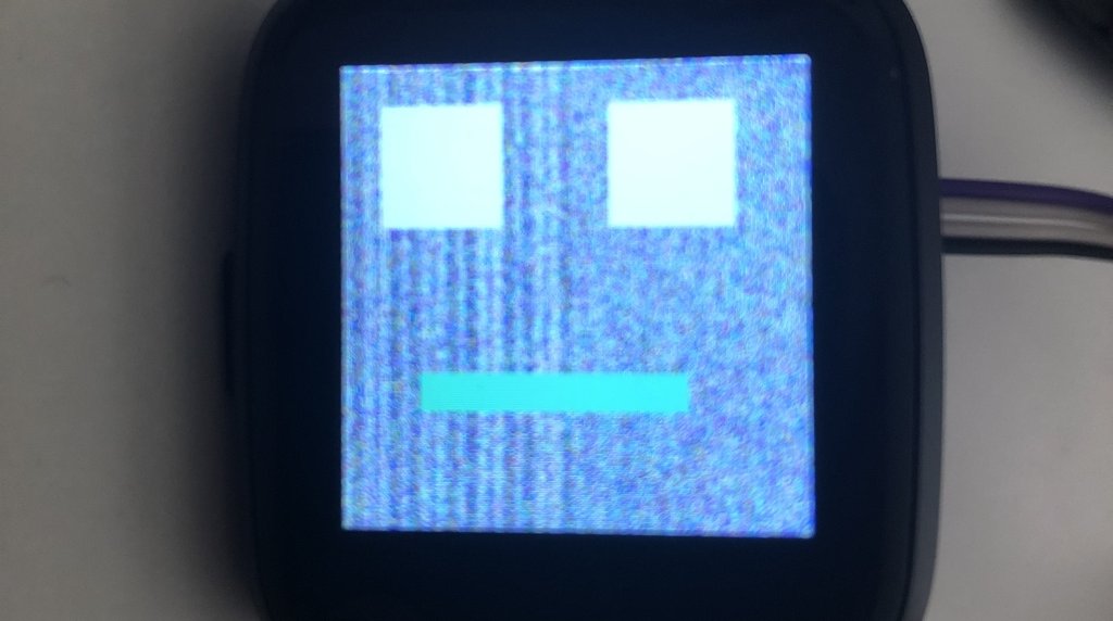
A bit more effort and a detour into demoscene research and I got that neat twister you saw at the top of the screen!
SPI is dead, long live SPI.
Remember how I mentioned earlier that SPI access from the LCD task is way faster? Well, I wanted to animate my twister and that’s when I ran into troubles, because screen updates were taking agonizingly long. It wasn’t so much an animation as it was a slideshow. As a result I was forced to cut the SPI task I worked so hard on out of the equation and give the SPI hardware address space over to my LCD task instead. This gave me the smooth animation I was looking for, but it was kind of disappointing to have to do. oh well!
There’s a long way to go
Getting this project from where it is now to a fully functional smartwatch OS would be quite the endeavor. We’d need to bring up i2c to talk to the touch screen and other sensors, get the SPI flash working, implement a proper graphics stack. We’d need to write apps for the darn thing, or even have a watch face of any sort. We’d need to optimize everything for battery consumption as much as possible. All of this, and I haven’t even mentioned bluetooth, which would require finding a good bluetooth stack written in rust, or making one.
That’s far more than I care to do myself, though it might be possible to nerdsnipe me into helping if others want to work on it too. No promises.
Still, I hope you learned something, or just found this interesting. I know I sure have!