SSTV Tx/Rx with a Pi and an RTL-SDR
It turns out that transmitting and receiving SSTV signals is pretty easy, using just a raspberry pi as a transmitter and an RTL-SDR as a receiver. There are a few programs which you’ll need to install before you begin:
-
rpitx includes tools for encoding and transmitting SSTV signals with a raspberry pi. This should be installed on the pi itself.
-
gqrx is a graphically controlled SDR program, which will be used for receiving and recording the SSTV signals. Put this on whatever computer your SDR is hooked up to.
-
qsstv is an open source cross-platform SSTV decoder which can decode directly from recorded audio.
-
imagemagick will be used for converting images to a format rpitx can understand.
If you’re on linux, the last three may be available in your distribution’s package repositories; make sure to check those before wasting time downloading and installing them manually.
Additionally, be aware that this may not work with the Raspberry Pi 2 or 3. Stick with a Pi A/B/B+ for best results. A Pi Zero may also work, but I haven’t tested that.
Scroll to the bottom for a demo video of GQRX and QSSTV in action, using the realtime decoding technique described towards the bottom of the post.
Transmitting SSTV
1. Resize your image to 320x256 pixels. I did this by cropping my image with imagemagick. This command will resize, maintaining aspect ratio of the input, and then crop the result to get to 320x256 pixels:
convert <input> -resize '320x256^' -gravity center -extent 320x256 <output>
2. Convert your image to an 8 bit depth RGB file.
convert -depth 8 <input> <output>.rgb
This step can be combined with the previous step.
convert <input> -resize '320x256^' -gravity center -extent 320x256 -depth 8 <output>.rgb
3. Convert the rgb file to a .st file for rpitx, using the included tool.
pisstv <input>.rgb <output>.ft
4. Broadcast with rpitx
sudo rpitx -m RF -i <input>.ft -f <frequency in KHz>
Receiving SSTV
Capturing and recording signals will be done with GQRX. SSTV decoding will then be done afterwards with qsstv.
Recording with GQRX
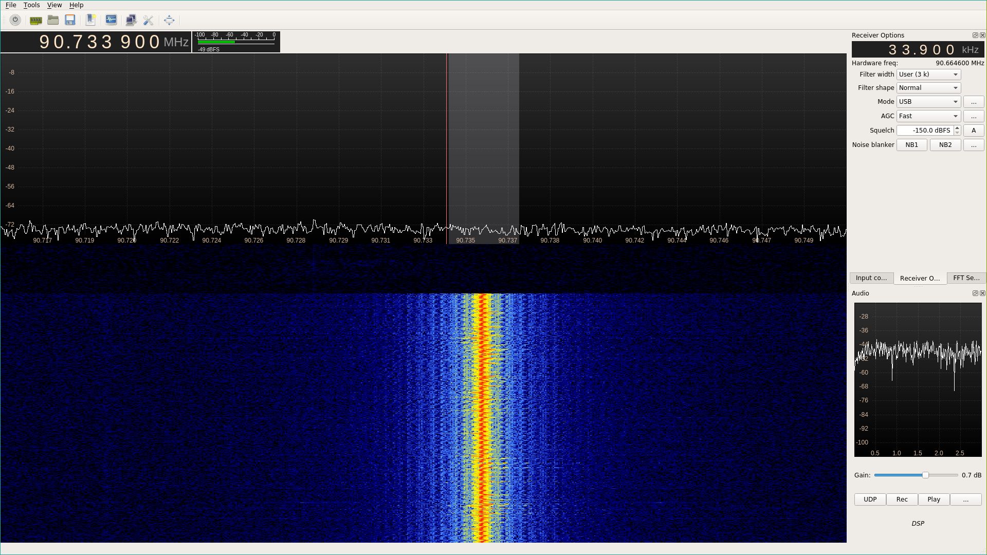
1. Open GQRX. Tune to the frequency you’re transmitting on
2. Set your decode mode to USB, and drag your filter width to 3 k.
3. Begin transmitting from your Raspberry PI. We won’t decode this initial broadcast. Instead we’ll be using it to properly tune our receiver.
4. Center your decode filter area over the signal seen in the waterfall. You should have something which looks similar to the image below.
5. Adjust your audio gain in the bottom right to be be audible. Hit “Rec”, and then restart your SSTV transmission. Audio will be recorded to a wav file in your home folder. Stop the recording after your SSTV transmission completes.
Decoding with QSSTV
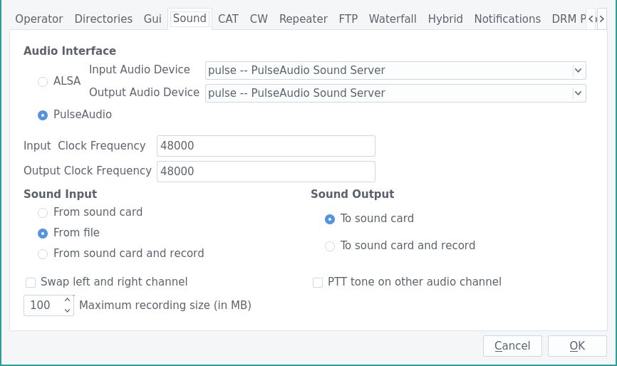
1. Open up QSSTV. Navigate to Options -> Configure. Go to the “Sound” tab, and set the sound input to “From file”.
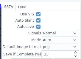
2. Go back to the main QSSTV screen. Configure your SSTV settings to match the image below.
3. Click the “play button” icon in the top left corner. You’ll be prompted to select a wav file to decode. Navigate to your GQRX recording and select it.
4. Wait. Decoding may take some time and appear to freeze , but if all goes well you should have a fully decoded SSTV signal.
Realtime Decoding
It’s actually possible to decode SSTV data in real time with a slight modification to the recording and decoding process! You’ll need to install netcat and sox for this to work.
1. In GQRX, select the “UDP” option instead of the “Rec” option. This will make GQRX send audio data as 1-channel raw pcm s16le data over UDP to some address. The default address is localhost on port 7355, but you can configure that by clicking the “…” button next to “Play”.
2. Now we need to make a FIFO for QSSTV to read from. Since QSSTV looks in $HOME/audio for files by default, that’s where I put mine, but you can put it anywhere.
mkfifo $HOME/audio/realtime
3. Use the following command to listen for data from GQRX and write it to the FIFO as it’s received. The command will stop after you turn QSSTV’s decoder off, but you can pause/unpause/restart GQRX as much as you want with no problems while this is running.
netcat -l -u localhost -p 7355 \
    | sox -r 48000 -e signed -b 16 -c 1 -t raw - -t wav - \
    > $HOME/audio/realtime
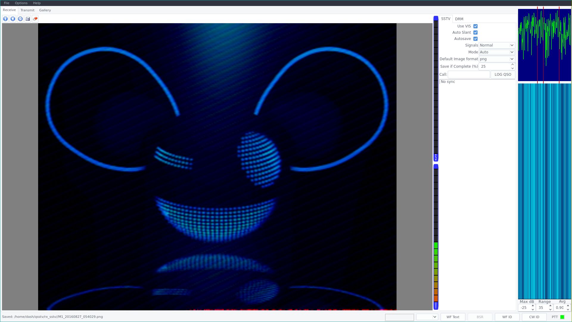
4. In QSSTV, click the “play button” icon as before, and select the “realtime” file for playback. The file size will show up as 0 bytes, that’s normal, but at this point QSSTV should be receiving data. and displaying it in its waterfall on the right hand side of the screen.
Demo
Here’s a demo video of the process. Notice how QSSTV has three red bars. When the decode initializes, the lowest tone should peak at the left red bar, and the highest tone should peak at the right red bar. If they’re significantly off from where they should be, and you aren’t getting an image decode (or the image looks wrong), that’s how you know you need to adjust your tuning a bit more.